
Focal length (FL) affects the field of view and magnification, as it is one of the
most important parameters when choosing optics.
Focal length refers to the distance between the main plane of the lens and a particular point where the light is focused from infinity. Below, Figure 1 visualises how the focal length, marked with f and f ′, affects the image height. A long focal length magnifies more than a short one (Greivenkamp 2004).
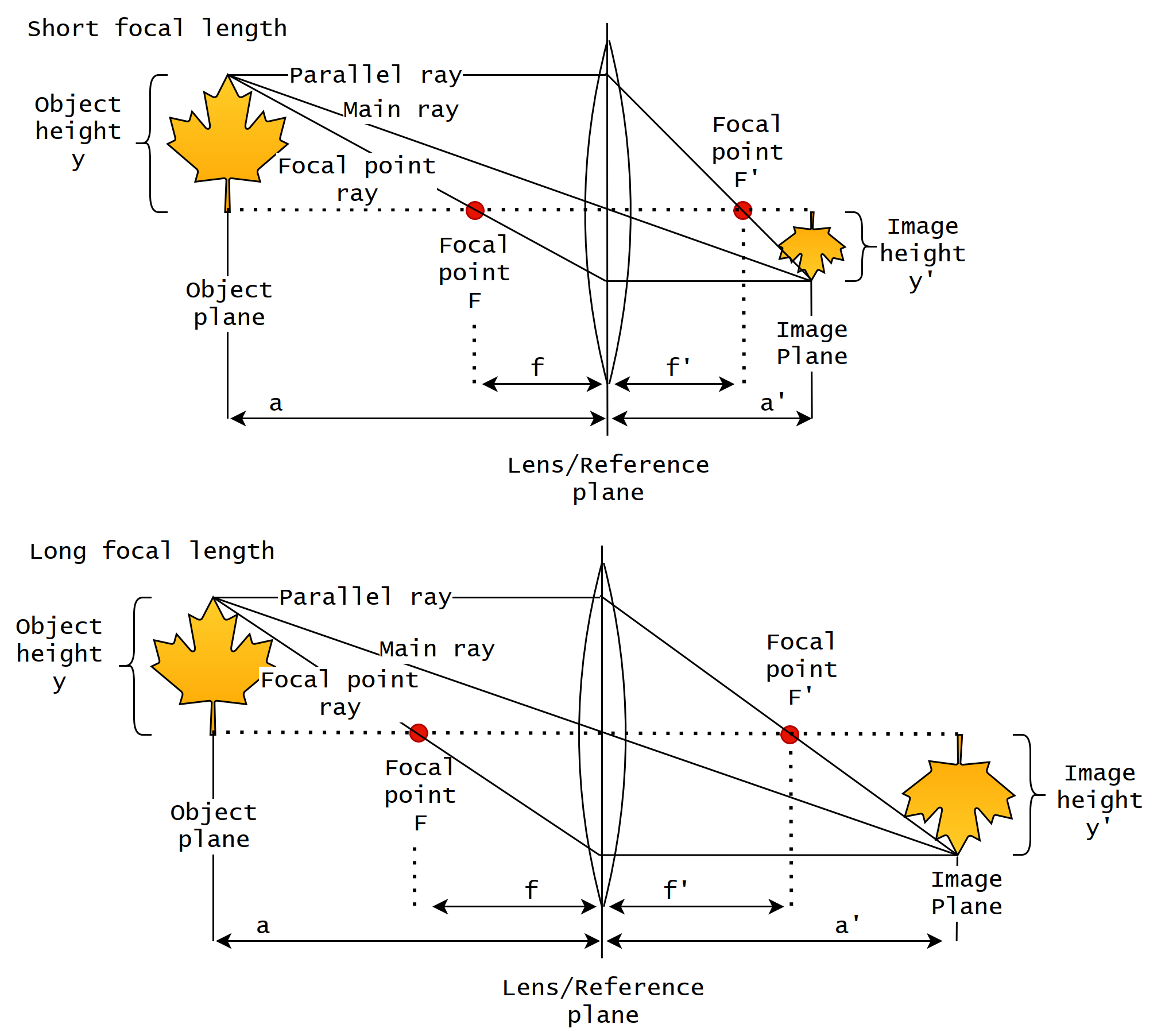
The working distance, object size and focal length affect the magnification. From above, Figure 15, we can see that a longer focal length increases the magnification without extending the working distance a. Magnification β can be approximated for a non-complex optical setups as follows (Greivenkamp 2004):
(1) 
For thin lenses:
(2) 
Below, Figure 2 explains the lens opening angles and their relations with the horizontal, vertical and diagonal field of view (FOV). By looking at the angles and rays of the image, we can see that the relation between the field of view and working distance correlates; the image field of view decreases while the working distance shortens and vice versa.
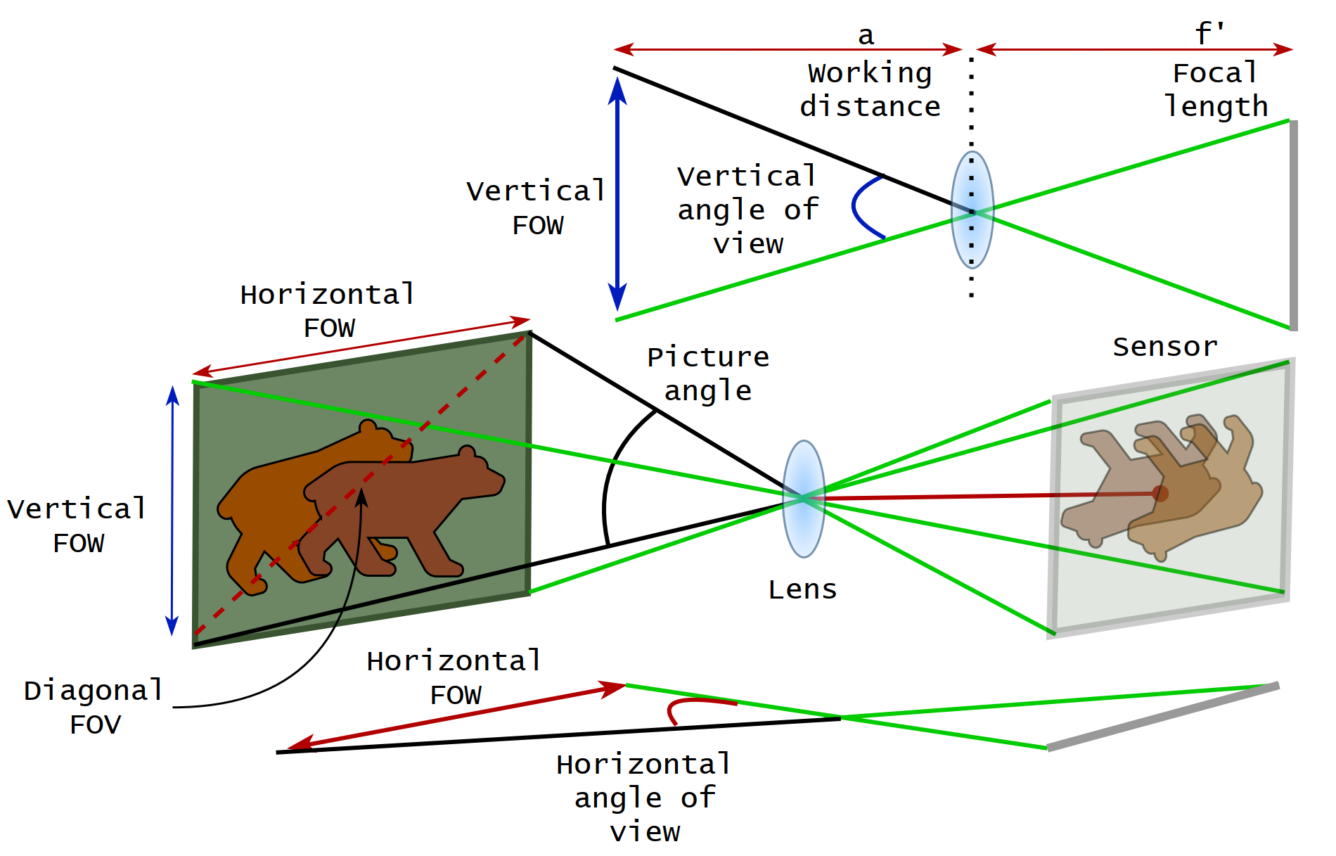
The relation between the opening angle and focal length is the opposite; the larger the focal length, the narrower the opening angle. Most of the lens parameters described in Table 2 (Post 3.1) can be calculated either with pen and paper or using services like Vision Doctor (Doctor 2022) or sensor manufacturers’ web tools, which are provided for designing imaging systems.
While there are many parameters to consider, the infrared (IR) cut and possible colour corrections are the least worth mentioning features. Suppose an imaging system is for spectral imaging, and the interesting wavelength range is in IR. It might be good to exclude lenses designed to block IR light or lenses that have some other undesirable colour corrections by default (Greivenkamp 2004; Stemmer 2022).
Found something useful? Wish to cite? This post is based on my dissertation. For citations and more information, click here to see the scientific version of it.
References
Greivenkamp, John, E. 2004. Field Guide to Geometrical Optics, Vol. FG01. SPIE, https://doi.org/10.1117/3.547461.
Doctor, 2022. Vision doctor, home page. https://www.vision-doctor. com/en/. (A private, independent, non-commercial website project providing solutions to machine vision. Accessed on 4.5.2022).
Stemmer 2022. Stemmer Imaging, The Imaging and Vision Handbook. URL:https://www.stemmer-imaging.com/en/the-imaging-vision-handbook/.